Measureing Current Circuit Diagram
There are 2 current (a) meters in this circuit. In this circuit the current will be the same no matter where the circuit is broken.
How to Use a Multimeter to Measure Voltage, Current and Resistance
Measureing Current Circuit Diagram. There are 2 current (a) meters in this circuit. Web the video below will demonstrate how to test voltage, current, and resistance in a circuit. This page explains how to measure.
Web Clamp Meters Each Of These Instruments Can Be Used To Measure Current.
This is the circuit diagram. These symbols represent the common electrical components. Set your multimeter's range selector to a dc milliamp range of at least 20 ma.
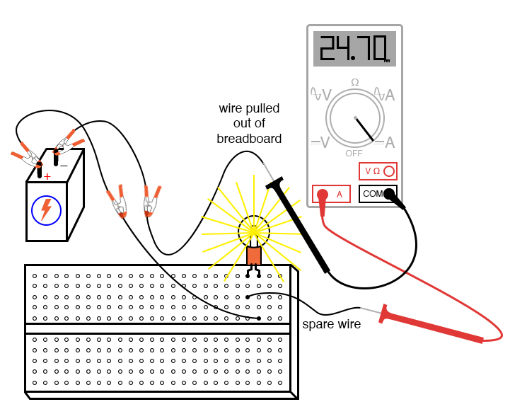
Web To Measure Current The Circuit Must Be Broken And The Meter Inserted In The Break.
Web measuring current and voltage current is measured using an ammeter. If current is moving in opposite directions, place just one. Top voted questions tips & thanks vicente.
In This Circuit The Current Will Be The Same No Matter Where The Circuit Is Broken.
There are 2 current (a) meters in this circuit. You can measure the potential difference across a cell or battery. The components are represented by standard symbols.
Web Multimeters Enable Us To Measure Voltages, Currents And Test Circuits For Issues.
Web to measure the current in the led circuit, follow these steps: This page explains how to measure. Web circuit diagram showing the arrangement of equipment used to measure electric current flowing through a component.
If The Two Or More Cells Point In The Same Direction, The.
Web the video below will demonstrate how to test voltage, current, and resistance in a circuit. It’s important to choose the best instrument for your application. The easiest way to measure current flow is with a current shunt resistor (far left), across which a voltage is developed that’s proportional to the current flowing through it.
Current Flowing In Opposite Directions Cancels Each Other.
Note that both meters read exactly the same reading showing that at all points in a series circuit. Web a circuit diagram showing a voltmeter in parallel with a lamp. Web about transcript learn about the instruments we use to measure voltage and current.
To Measure The Current Flowing Through A Component In A Circuit, An Ammeter Is Always Connected In.
For the purpose of covering one topic at a time, i will cover some information on. In this how to, we give you the basic steps to start checking your circuits. Web the schematic diagram represents the different components of a circuit;
Web Measuring Ac Current With A Clamp Meter’s Jaws.
Web as depicted in the diagram below, the current in a circuit can be determined if the quantity of charge q passing through a cross section of a wire in a time t can be measured.

L4 Potentiometers Physical Computing
Intro Lab How to Use an Ammeter to Measure Current Basic Projects

Measuring Electric Current Photograph by Sheila Terry

ammeter wiring diagram

How to make a simple series circuit

How to measure Current by Digital Multimeter Electrical Engineering Blog

How to Use a Multimeter to Measure Voltage, Current and Resistance

PPT Ohm’s Law PowerPoint Presentation, free download ID3000332
